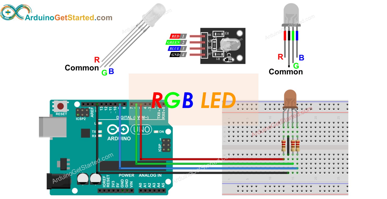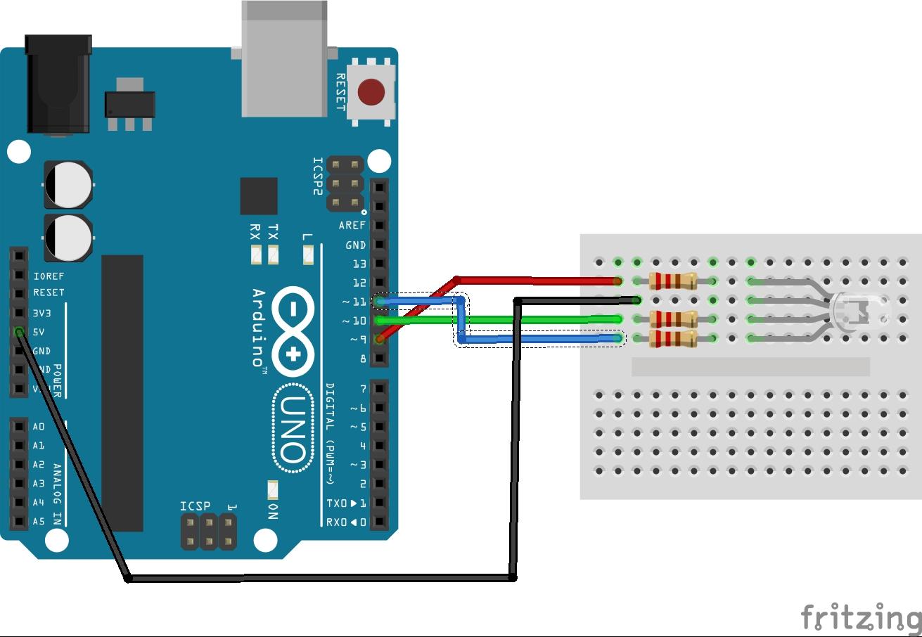
- ARDUINO RGB LED TEST INSTALL
- ARDUINO RGB LED TEST SERIAL
- ARDUINO RGB LED TEST DRIVER
- ARDUINO RGB LED TEST CODE
Looks like a textbook ‘Arduino’ type implementation of the 16Mhz Atmega chip, i just did something similar as a home project, admittedly not using DMX but oldschool beat detection using the analogue ADC inputs on the chip Reply AFAIK, it’s mainly there for slew rate limiting. Most pixel controllers I’ve seen use a series resistor between 33R and 100R on each output. My guess is it was originally designed for the more common 5V LED tape, but they forgot to add protection when they modified it for 12-24V use.
ARDUINO RGB LED TEST DRIVER
Besides protection on that output (you can use one output of an RS485 driver for this with diodes etc) I would also protect the power supply from being reverse connected with a couple of diodes.

This looks like an Arduino project modified with mostly decent protection circitry. Even a simple resistor on the output of this unit could have limited fault current to a level where the output circuitry was protected. Inputs and outputs that interface with the real world should be protected from rogue external voltages. Specifically destroying a custom programmed microcontroller with no easy replacement. All it took was someone accidentally bridging two pads with a whisker of wire or solder, to completely destroy the unit instantly. The same sort of rogue voltage that might occur from a logic level data output that is in the direct vicinity of much higher voltage pads. The PTC self-resetting overcurrent thermistor and clamp diode approach is common on better designed DMX devices, as it protects the data inputs from rogue voltages.

It seems like the designer copied many protective elements from other designs, but then failed to apply the same concept to their own output. Both examples made a “random” color light show on my LED strip.
ARDUINO RGB LED TEST CODE
I also tried the original code from Arduino Addressable LEDs & Splendid Projects page which I modified to use 8 LEDs instead of one. After restarting Arduino IDE, I opened File->Sketchbook->Library->Adafruit_NeoPixel->strandtest sketch example file. After downloading, I had to rename folder to ‘Adafruit_NeoPixel’ and move it to Arduino Libraries folder.
ARDUINO RGB LED TEST INSTALL
So I needed to get the library from and install it according to instructions. In the first test I fould out that in addition to the source code I also needed NeoPixel Arduno library. That page had an example source code that looked to be useful and simple wiring instructions. To get easy start, I planned to follow instructions fro Arduino Addressable LEDs & Splendid Projects page. And there are many Arduino tutorials for WS2812. After some looking on vailable examples and technical data on the LEDs, I planned to use Arduino (Arduno Uno), because it’s 5V power and 5V logic level is directly suitable. I planned to use either Arduino or ESP8266 to control those LEDs.
ARDUINO RGB LED TEST SERIAL
ThoseWS2812 LEDs are powered with 5V – 7V power source (60 mA power consumption) and are controlled through a serial bus (one control signal). The integrated controller chip allows you to change the color of the LED and address each individual LED.

WS2812 neopixels are addressable RGB LEDs. Addressable LED promise is to be an easy way to add complex lighting effects to any project. By varying the level of red, green and blue (RGB) per LED many color combinations can be made. An addressable RGB LED strip is a long flexible strand of LEDs each of which can be individually set to a certain color (hence: addressable). To test controlling WS2812 RGB LEDs I bought a cheap addressable LED strip. These LEDs can be individually controlled to display red, green, and blue, but interfacing them with a microcontroller or computer. RGB LEDs are awesome – especially the new, fancy ones with the WS2812 RGB LED driver. Arduino, DIY, Embedded Development, LEDs.


 0 kommentar(er)
